Previously, I have written about the use of a modeling language and the practical usage of the TOGAF Enterprise Continuum to classify architectural descriptions along different levels of abstraction. In this blog, I’m going to demonstrate how the content of these descriptions can be visualized with a standard notation. While TOGAF 9.1 provides the standard architecture development method (ADM), ArchiMate is the worldwide standard to model and visualize the content of enterprise architectures. Both are a public standard of The Open Group.
For this article, I’m going to show how the ArchiMate 3.0 specification supports you in modeling different levels of abstractions at Section 3.6, which I will map to the TOGAF Enterprise Continuum.

You have seen the distinction between Architecture Building Blocks (ABB), Solution Building Blocks (SBB) and Deployed Solutions. This distinction is similar to the distinction of logical (ABB) and physical applications (SBB) that are defined in the TOGAF Content Model. “At the Enterprise Architecture abstraction level, it is more common to model types and/or exemplars rather than instances” (ArchiMate 3.0, 3.6). For that reason, I’m going to focus on the ABBs and SBBs and how to represent them.
The ArchiMate 3.0 specification provides three approaches to distinguish these concepts, which I’ll present based on the application layer and my experience with each.
First approach – New architectures

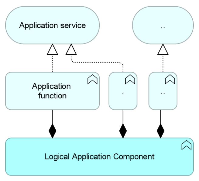
At the right of the picture above, you see the physical application component, or SBB, modeled as an application component that is assigned to the logical application component, or ABB, modeled as an application function. I like this approach to using the behavior column of the ArchiMate framework, as it includes the functions (rounded rectangles) that describe the logical architecture/ABBs, which are as a separated aspect next to the solutions. Different symbols indicate different meanings, making it easy to decipher.
This approach is well-suited to developing new project or program architectures. It starts with the definition of requirements and desired behavior of the future solution, and then assigns the SBB/physical application.
This approach can also be extended by adding application services that reflect requirements from an architecture context and can be understood as a conceptual layer. In that case, the application function(s) realize the application service(s) and can also be grouped to a logical application component by using a composition relation (as shown in the next picture). This pattern is useful to describe different levels of granularity, but the need for details might differ from project to project. You should include this consideration to avoid modeling overload for smaller scopes. The application of this approach can also be seen in the book by Bas van Gils and Sven: “ArchiMate – From Theory to Practice,” pg. 71.

Second approach – An additional layer

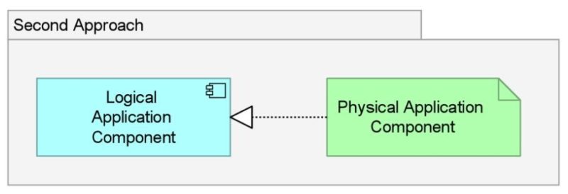
The second approach models the logical application component as an application component, realized by the physical application components, which are modeled as artifact (green element to the right). This approach holds the application layer reserved for the logical layer and the technology layer for the physical one. I am not a big fan of this approach, since I usually see applications modeled as application components and a lot of the ArchiMate examples on the web do the same.
On top of that, architects often have the need to model and analyze the environment of a specific application and its components being supported by technologies. This is not that convenient when using artifacts. Using the ArchiMate artifact concept usually refers to .exe, .jar or other files. So, this approach works best with the two other approaches listed in this blog when you want to show which files realize the application components that are described (and where they shall be deployed).

Third approach – Separate models
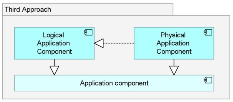
The third approach models logical and physical applications as application components, which can then be understood as two specializations of the ArchiMate application component. This approach is used in the reference model of IT4IT from the Open Group, and next to the first approach above the most often seen approach (personal perception). This is useful when you want to create complete different ArchiMate models for logical/ABB architecture and physical/SBB architecture.
Think of creating a reference architecture where you don´t show all the different business applications with their names, but rather one single element that represents some or all of them under the umbrella of “business applications.” It is also suited for documentation purposes to avoid bringing too many different new concepts into the picture. Using this approach, the whole ArchiMate layer with all concepts can be used in both levels of abstractions (ABB and SBB).
What is left?
Now you have seen three approaches the ArchiMate framework offers to describe your architectures, according to the TOGAF Enterprise Continuum of Architecture and Solution Building Blocks with a standard notation. Since it is a framework, you should make sure to use what is useful for you. In the final blog of this series, I will complete the mapping of ArchiMate to the TOGAF Enterprise Continuum by connecting the first of the three approaches to the Deployed Solutions.
— Learn more about the ArchiMate standard, or if you want to get trained, please visit our Academy, where you will find trainings for TOGAF, ArchiMate and more.