Architects need to reduce the complexity of creating diagrams. Creating overly complex diagrams (too many different types of concepts) often confuses stakeholders. Each viewpoint needs to address a specific concern, e.g. a capability map that shows the capabilities of the organization. In this blog I’ll focus on the application layer and provide practical examples using the viewpoint creation pattern. The examples are quite generic and they’re meant as a starting point for professionals looking to learn more on the subject.
ALSO READ: A pattern for sizing ArchiMate diagrams
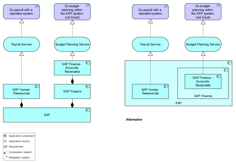
Structural relationships model the static construction or composition of concepts of the same or different types. The application components viewpoint can be set up to show the hierarchy of application components, their application services and which requirements are realized by the application (components) or their services. You can use it to create diagrams that simply show the components of an application. In this case, it supports you to add new elements to your model in a guided way. You can also show the requirements a new application (service) shall fulfill. The focus of this viewpoint is on one application, not on the dependencies or support for other application components. It is similar to the application structure viewpoint mentioned in the ArchiMate standard, but more restrictive, focusing on the hierarchical structure of one application and showing which requirements the new application shall realize.
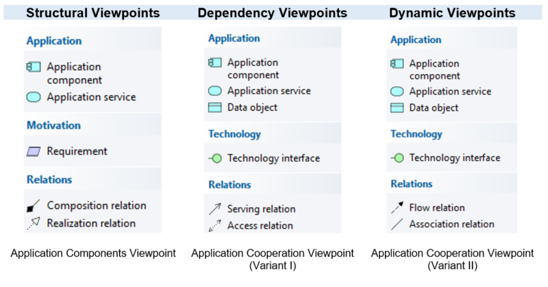
Compared to the whole ArchiMate standard, which includes 59 concepts and 13 relation types, this viewpoint only allows the creation of 3 different concepts and 2 different relationship types. This makes it even less complex than a BPMN process viewpoint. An example of the application components view is shown below. On the right-hand side, I made use of graphical nesting based on the composition relation to show an alternative graphical representation.
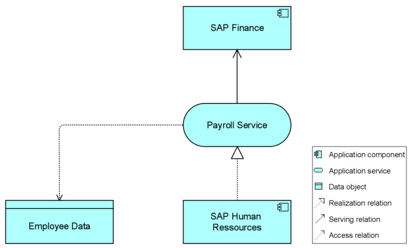
Dependency relationships model how elements are used to support other elements. Employing the viewpoint creation pattern in this case will allow for the creation of dependency viewpoints at the level of serving and access relationships. The dependencies between applications are often shown in application communication (TOGAF) or application cooperation (ArchiMate) views. Bottom line, they show what the cooperation between applications looks like. It can be expressed in a static way by showing the application services (what the application component does) and the data accessed. The example below shows that the Payroll Service is accessing (reading) the Employee Data when serving the SAP Finance application component.
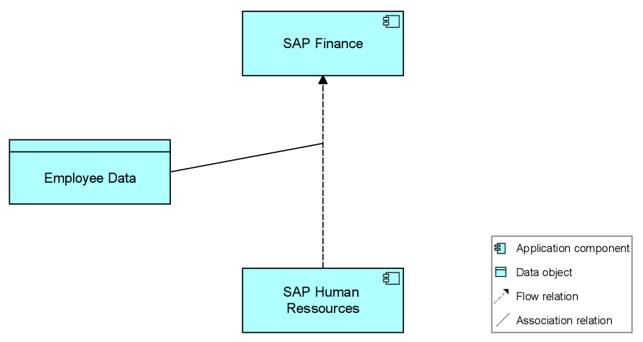
Dynamic relationships model behavioral dependencies between elements. The two relationship types are flow and triggering. Often, triggering is used between processes, while at the application layer we often see flow being used between application components. As an alternative to the viewpoint explained above, you can use the flow relationship to create an application cooperation diagram in a slightly different way. By not using the application service you hide information, but this can be an advantage when you want to show an end-to-end data flow for one data object across your application landscape. These diagrams can involve a lot of applications, so by not showing which services access which data, the diagram remains less complex. In the example below, we also make use of the association relationship, depicted as interacting with the flow relationship (allowed since ArchiMate 3).
Let’s recap. I applied the pattern described in my previous blog post to create ArchiMate viewpoints at the application layer. The pattern is very helpful to decide which elements and relationships are allowed in which diagram. Without such a pattern, for every constellation of concepts and relationships you will find a justification why they should be allowed in one viewpoint but not in another. So, this saves time when discussing which types of diagrams must be created in a standard way for projects.
These viewpoints also implicitly provide an order for creating elements at relationships. Often it is useful first to show the components and/or services of a new application and why it is needed. Stating why a new application or a new service is needed supports you in ‘selling’ your architecture, for example in a presentation to management. While creating this view, you add new information to your repository in a guided way. The application cooperation views then show the context of your new application – where they impact the existing application landscape.
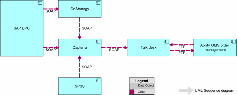
A useful addition to an application cooperation viewpoint is to show which technology interface is used (e.g. REST API, FTP etc.). Especially in the dynamic application cooperation viewpoint, with the flow relationship, you should think of a convention governing how many flow relationships you allow between applications. Adding one flow relationship for each data object gives you the option to add properties like exchange frequency, push/pull of data, but can also lead to very cluttered diagrams. An alternative is to only create one flow relationship per technology interface. For the big picture, this might be good enough to guide the architecture development. As a complementary diagram for more detailed solution design in projects, you might want to use UML sequence diagrams that show in detail the data flows from one application to another (including confirmation messages that are important for solution design but not at a higher architecture level). And of course, you don´t want to clutter your diagram by adding all concepts and relationships. Instead you can use coloring and labeling to show information from the architecture model – see example below.
The summarizing table below shows the three viewpoints presented above. You might want to create additional application layer viewpoints – for example, for logical architectures, by using the application function instead of the application component concept. Feel free to try out this viewpoint creation pattern yourself, it is a strong and useful guidance!
DOWNLOAD: Why ‘future state design’ is a key differentiator in Application Portfolio Management